
MIM-Manufactured Stainless Steel Trigger Arm, Verified by 3D Scanning

The challenge
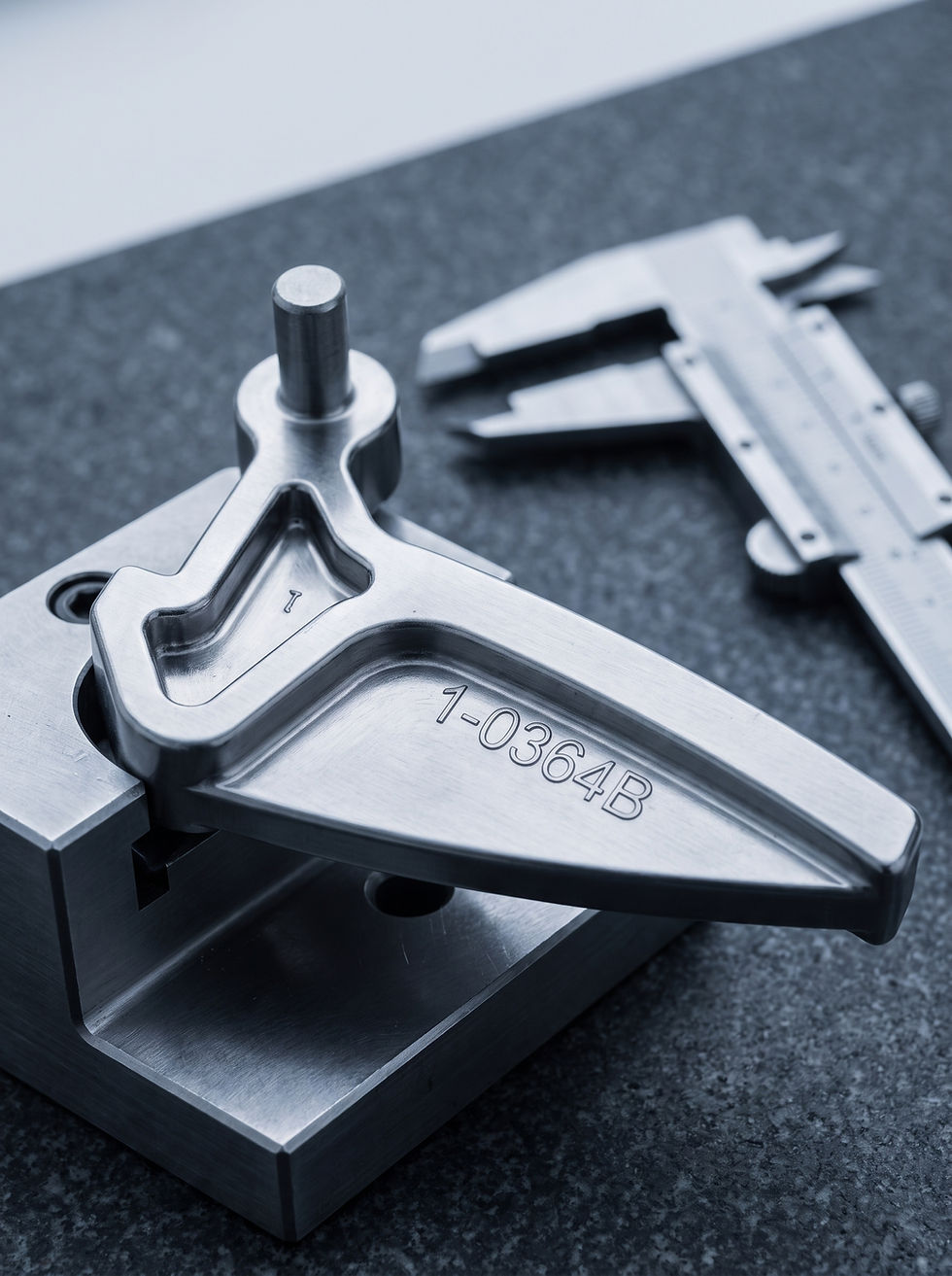
The trigger arm is a relatively small part, but it places high demands on:
-
Geometric accuracy
-
Repeatability across the production series
-
Surface quality
-
Dimensional stability after sintering
Several of the functional areas carry tolerances down to ±0.05 mm, which requires full control over the entire production chain — from feedstock and tooling through to debinding and sintering. Because MIM parts shrink in a predictable, controlled way during sintering, this shrinkage has to be compensated for already in the tool design and then confirmed on the finished part.
Traditional measurement methods — calipers, gauges and single-point probing — can verify individual dimensions, but they don't reveal the full picture of a complex geometry. For a part like this, point-by-point measurement risks missing form deviations between the points that are actually checked.
The solution
Metal Injection Moulding (MIM)
MIM lets us produce the trigger arm as one finished part, with:
-
Complex geometry formed in a single step
-
Integrated functions and features — no assembly of sub-components
-
Minimal secondary machining
-
High dimensional accuracy
-
Consistent quality across series production
The result is a strong, precise stainless steel component that is ready for assembly straight from production. Because the part is moulded close to its final shape, material waste is low and the geometry stays consistent from the first part to the last — a key advantage when the same component is produced in volume.
Quality assurance with 3D scanning
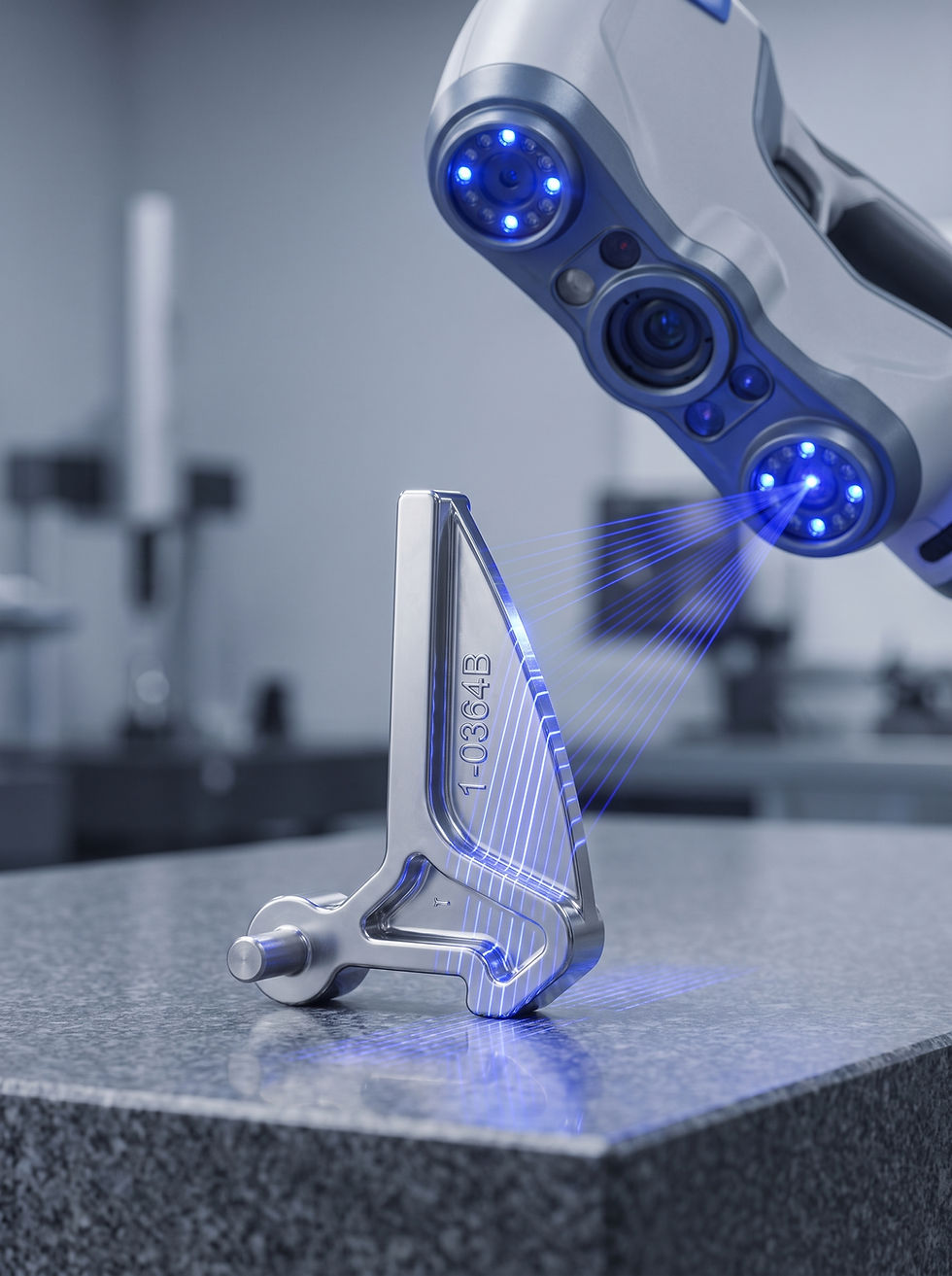
After production, the trigger arm was digitised with a SIMSCAN Gen2 handheld 3D scanner. The scan generates a complete digital copy of the part — a dense point cloud covering the full surface — which is then
compared directly against the original CAD model.
This full-field method makes it possible to verify:
-
Critical dimensions
-
Form deviations
-
Shrinkage after sintering
-
Geometric tolerances
-
Complex 3D geometry
across the entire component — not only at a handful of selected measurement points. In practice, that means a deviation hidden on a curved surface or a radius transition is caught, where single-point measurement might have passed the part.

Colour map reveals deviations down to a few hundredths of a millimetre
The scanned model is overlaid on the original CAD geometry, and the result is visualised as a colour map:
-
Green — within tolerance
-
Blue — below nominal dimension
-
Red — above nominal dimension
On this trigger arm, the analysis showed that the component sits very close to the CAD model, with minimal deviations across the whole part. With the SIMSCAN Gen2 capturing data at metrology-grade accuracy, the comparison resolves differences down to a few hundredths of a millimetre.
This gives both manufacturer and customer documented proof that the component meets its specified requirements — a verifiable digital record of quality, delivered alongside the finished part.

HQ
Pamatek A/S
DK29841446
Bækgårdsvej 72
4140 Borup
Tel.: +45 70 233 637
© 2026 by Klamer Dueholm Fractionals.
From complex design to documented precision
At Pamatek, we produced this trigger arm in AISI 304 stainless steel using Metal Injection Moulding (MIM) — a process that lets us form intricate metal parts in a single operation, with the strength of a fully sintered alloy and the geometric freedom normally reserved for plastic injection moulding.
The component combines several demanding features in a small footprint — detailed geometries, thin walls, precise radius transitions and tight functional tolerances — which makes it an ideal candidate for the MIM process. Once produced, every part was verified with advanced handheld 3D scanning to confirm that the finished geometry matches the design intent across the entire component, not just at isolated measurement points.